Saturday, August 4, 2012

How To Use Excel To Generate Code For LCD & LED Display

This tutorial is for those who know How to use 16x2 LCD or How to make LED display or How to make Propeller display.

By using this you will also learn How to print Custom Characters in LCD like printing HINDI characters or any other language. WOW!!!
16x2 LCD hindi16x2 LCD custom character
LED matrix
So you are using the sample code :P till now, Its time for you to make your own Excel code.
Its more easy and gives  you much more feeling about how things are working.

This tutorial covers generating code for
1. Normal LED Array
2. 16x2 LCD
3. LED diaplay
4. Propeller Display or Spin LED

Things you need
1. A computer having MS Excel or any other SpreadSheet Software like LibreOffice.
2. An  AVR board. (You can buy one online from sites like www.robokits.com)
you can download the files from here, LED display.c   LCD display.c   Propeller.c

You should have some basic knowledge of EXCEL like cells, functions and some formulas, Conditional Formatting,decimal numbers, binary numbers, etc

Open Excel. The method/trick that we'll use to color the cells of EXCEL is called "Conditional Formatting".
By using this you can specify the conditions according to which EXCEL would color the cells automatically.
For e.g. if any cell is having number > 5 then that cell color would become green.
In  MS EXCEL 2007 and MS EXCEL 2010 this option is shown below.
EXCEL 2010 Conditional Formatting
For LibreOffice the option is shown below.

LibreOffice Conditional Formatting

And for MS EXCEL 2003 the option is shown below.
EXCEL 2003 Conditional Formatting
 I'll be using EXCEL 2010.
 Now select an area in EXCEL on which you would like to apply "Conditional Formatting".
EXCEL select area

Now click "Conditional Formatting" -> Highlight Cells Rules -> Equal To... 

EXCEL conditional formating
Now type '1' as shown in the box.
Because I want that whenever there is number  '1' in any cell it should become 'green' colored, so choose 'Custom Format...'
EXCEL conditional formating

choose any color like green or red etc and click ok. Click ok one more time.
EXCEL format colours

Note that in every cell wherever there is number 1 its color has been changed to green, rest cells are unchanged.

EXCEL conditional formatting

Since we are generating a code for LCD or LED which are square in shape so lets change the column width of cells.


Set it to 3 or 3.5
EXCEL column width

See now its looking like a real character which can be displayed on a LCD or LED display.
EXCEL conditional foramting


But still to resemble the background color to that of a DOT PCB you may wish to change the background color.

If you don't know about basics of a Micro Controller then please read this Basics Of Micro Controller.
So now you know that there are 8 pins in a PORT of MCU,.
When the 8 pins are connected to 8 LEDs then to glow
LED1 you have to write  PORTB=1;  //Assuming that you are using ATMEGA8 or 16 MCU
For LED2 => PORTB=2;
To glow 1st and 2nd LED PORTB=3; to glow all LEDs PORTB=255 and so on......
As an example you can see the below image


Now you can create any Alphabet or a Custom Chartacter, but how are the numbers coming automatically???
EXCEL code for LCD custom character


Here's the trick

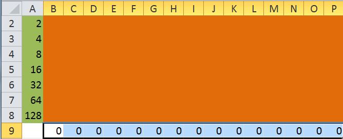
  • Select the 'cell' in which the code has to come (here B9)
  • Select the 'Formula Bar' and enter the formula =B1+B2*2+B3*4+B4*8+B5*16+B6*32+B7*64+B8*128
  • Press ENTER.

You'll see a '0' in that cell, as I have not entered any number in any cell of second column.


Now repeat the step for all other columns!!!


Just kidding :) you don't have to that,  just drag the 'small sqaure' to P9, the formula will be automatically changed according to the columns.


After that it will look like this.
 

 Now copy the generated 'Decimal code'.

You may wish that there should be a way that a  comma (,) can be added automatically, so that we can directly paste it in any .c file directly without editing.
Here is the trick....
Add  &","  at the end of the formula. Easy enough..... :)
EXCEL code for LCD custom character

Now the code is generated along with commas in between.


THANKS FOR VIEWING THIS TUTORIAL 
Read more ...

Thursday, July 26, 2012

Using PWM on atmega16


Things u need
  1. A  MCU (atmega16 or atmega8)
  2. A led and/or motor and/or dc fan.

Difficulty Level
Easy from application point of view, a bit typical from programming point of view.

Time Required
If you are using the code given my me, then 1/2 or 1 hour.

Concept
PWM means Pulse Width Modulation.
PWM


Before lettting you what does it mean, let mew ask you a simple question, How to regulate a motor's speed?
You may answer that using a variable resistance, but what if I need to do it by using programming. Here PWM comes in play. One more famous example is  How to show the dimming effect in a led. Again PWM the answer.
What PWM does is that instead of sending a continuous supply of voltage to load (led, motor, dc fan, etc) it sends the supply in PULSE , that’s why the process is called PULSE WIDTH MODULATION.
Now if we have to control the speed of motor or intensity of led then we have to control the WIDTH of the PULSE.

There are two things to learn to use PWM,
  1. Timers
  2. OCR register
There are two internal Timers in atmega8, T0 (pin6, D4) and T1 (pin11, D5) and in atmega16 also T0 (pin1, B0) and T1 (pin2, B1).
These timers once activated run continuously from 0 to 255 (8 bit) as long as the program runs.

There are 3 OCR registers in both atmega8 as well as atmega16.
In atmega8 pin15 is OC1A, pin16 is OC1B, pin17 is OC2.
In atmega16 pin18,19,21 are OC1A,OC1B and OC2 respectively.
The PULSE WIDTH is set by these OCR registers only.
The time upto which MCU will send supply depends on what is value of OCR register.
Suppose the value of OC1A is 128 then while the timer which is running is between 0-128 the MCU will send supply to pin19 (atmega16) or pin15 (atmega8)   and when its between 129-255 the MCU will not send supply to that pin, so the bottom line is that for exactly half time pin is getting the supply and for exactly half time the supply is off, so the effective voltage reduces from 5v to 2.5v. The motor will run slow , the led will dimmed.

Below is the code shown for using PWM
This will make the LED to glow from minimum intensity (OCR1A=0 ) and then the increases  upto highest intensity (OCR1A=255) . You can add delay to increase the time required to complete one cycle.
To get full code download the link.
Download this link which has the required Header Files (timer0.h,timer1.h,timer0.c,timer1.c).


Read more ...

Monday, July 23, 2012

Measuring tempearture using LM35.


Things you Need

  1. LM35 IC
  2. Male & Female Burg-Stick (optional if using breadboard)
  3. Solder wire & Soldering Iron
  4. Connecting Wire

Time Needed

1-2  hour depending on how good & fast you are at soldering. If using breadboard to make temporary circuit it will hardly take an hour.


Difficulty Level

Easy :)


The pin configuration of LM35 is shown below.


Step 1:
Insert the female burg-stick to a small piece of PCB (I do so to make circuit more stable and durable) or insert in a breadboard. Then Solder it. Also insert the Male burg-stick and solder it.
Now insert the LM35 IC in that female stick.


Step 2 (If using AVR-KIT from BRiCS):
Connect pin1 of IC (VCC) to pin2 of stick, pin2 of IC (VOUT) to pin4 of stick, pin3 of IC (GND) to pin1 of stick.


Step 2 (If using BreadBoard):
Connect pin1 of IC (VCC) to VCC of MCU (pin10 in Atmega16,pin7 in Atmega8), pin2 of IC (VOUT) to any ADC pin (port-A in Atmega16, port-C in Atmega8) of MCU, pin3 of IC (GND) to GND of MCU (pin11 in Atmega16,pin8 in Atmega8).

Step 3:
Connect the stick directly to kit . Those using breadboard don’t need to anything.

Hardware part is done. :)


Coding & Concept:
Lm35 IC gives a linear output voltage in Degree Celsius.
There is rise of 10mV of output voltage for one degree rise in temperature. This means,
500 mv == 50°C       100 mv == 10°C     and so on.

Datasheet tells that it may measure tem[erature from -50°C to 150°C!!  :O
 We know that (I suppose :P) in avr MCU the ADC reading is in 10 bit, that means

1024 adc reading = 5 volt = 5000 mv = 500°C  (not measurable).
1 adc reading = 5/1024 = 0.0049 volt = 4.9 mv = 0.49°C
x adc reading = 0.0048828*x volt = (4.8828 * x )°C
.

So we have our formula ready i.e. Temperature =   (4.8828 * adc_reading )°C.
The coding is shown below.


Now lets see the output.


Ok but now how can I produce a high temperature, lets bring the soldering iron (which I left on) near the IC, It should increase the temperature.


See its working. It rised to 41°C from 31°C.

You can make this circuit on PCB also.

We can use two 7segment LEDs also to display the temp, it looks cool :)

To learn how to use 7segment LEDs please have a look on my post "How to interface 7segment LED with Microcontroller"  Link will be updated soon.

To learn "How to control a fan speed according to temperature variation" please  refer to my post "How to use PWM with Atmega-16" Link will be updated soon.

If you have any other idea about what else we can do with the temperaure from LM35 in other projects please let me know, I'll try to include it here.
Suggestions And Queries are most welcome. :)  

Read more ...

Sunday, July 22, 2012

Circuit Diagrams

Read more ...

Saturday, July 21, 2012

How to make a Propeller Display

Things U Need
  1. 8 LEDs
  2. 8-10 meter long wire
  3. 11 Male Burg-Stick pins
  4. A small dot-PCB (optional)
  5. A wire-cutter (optional)
  6. Soldering Iron & Solder Wire
  7. AVR kit (Brics Students already have it) or a microcontroller+programmer+breadboard
Time Required
1-2 hours maximum.

Difficulty Level
Between easy-average.

Actually after reading this it'll be very easy to make your own propeller clock.
Step 1:
Take 8 leds and short the negative terminal of each led. If you want to make it easy then first insert every led in  a dot-PCB (first cut the PCB as shown in image). Make sure all leds are in same format (either +ve terminal upward or vice-versa). Now you can easily bend the -ve terminals of all leds  and solder them.
Step 2:
Cut the +ve terminals as shown in image, leave only 2mm approx. of terminal.
Step 3:
Take 8 wires each of 1 meter and solder each wire to each led's +ve terminal, and lastly tie the end with some wire so that the wires don't fly out when you are rotating them.
Step 4:
Take 11 male burg-stick pins, solder the 1st led's wire (starting from bottom) to 1st burg-stick pin, 2nd wire to 4th pin (yes leave 2 pins empty [only for BRiCS kit]) likewise other wires to remaining pins. Other Students can directly insert wires into breadboard (See the pins of ATMEGA-16, ATMEGA-8 first).
Step 5:
Now students having kit insert the pins into any port, others dont need to do anything else if you have already connected your MCU on breadboard to wires.
Construction part is over, isn't that was fast!
Now only programming part is left over
If you know the concept behind the working of propeller clock then skip to Step-6, else read this.
When the array of led is moving fast in circle then the leds which are blinking very fast gives a impression that some message is being printed because of Persistence of Vision (POV). 
Lets assume on time 't' the array is at 90 degree in air, all leds are glowing, after a milli sec later when the array displays a little in clockwise direction then lets say from top 4th led is glowing, similarly for 3 more times 4th led is glowing and 4th time again all led glows.
Can you guess what will happen?
You will see that letter 'H' being printed in air.
Step 6:
Produce the "decimal numbers" of the required message that you wish to print in air, by using excel if you dont know how to do it dont worry read this post "How To Use Excel To Generate Code For Propeller Clock & LED Display".
lets assume you wished to display a heart, the decimal code for heart is 6,15,31,62,124,62,31,15,6,0. You can guess how this works by seeing the image below or else read the above post "How to Use Excel..........".
The code will be:
char a[]={6, 15, 31, 62, 124, 62, 31, 15, 6, 0, 0, 0, 0, 0, 0, 0, 0, 0, 0, 0}, i=0; 
// extra zeros so that two hearts dont overlap
for(i=0;i<=20;i++){
  PORTB=a[i]; _delay_ms(5); // if it flickers then use _delay_us(500) or even low.
}
To get complete .c file click download.
Read more ...

Introduction to MCU [MicroController]- Atmega-16 & Atmega-8


There are many MCUs available in market.
Some famous are AVR, 8051, pic,ARM, etc
We'll be using atmega series (atmega-8, atmega-16,atmega-32,etc).

In atmega-16 there are 40 pins, 4 ports, PORTA, PORTB, PORTC, PORTD.Each port has 8 pins. So you got a total of 32 input/output pins. The rest 8 pins  are 2-VCC, 2-GND,2-XTAL (crystals) 1-AREF(reference),1-RESET. 

Each PORT has 3-registers, for e.g. port-A has PORTA, PINA, DDRA. 
Each register has 8 BITS, as you can see in the following image. By default all 8 BITS are zero.
Lets talk about port-A, same will be for others also.
NOTE: port-A & PORTA are different terms. Dont confuse between them.

The PORTA & DDRA registers are writable that means we can change there value by PORTA=8; or like any value between 0-255. But PINA register is not writable, we can only read from it.
Read from it? Wait a min.... I didn't got it.
We'll see it in a couple of minutes.
First you need to know that what is the role of DDRA register. Well you can see it as a switch, if any particular bit's value is one then the respected bit's of PORTA & PINA are shorted. It means the value of PORTA gets copied to PINA if DDRA is 1. 


If you don't know how PORTD=12 make bit 2 and bit 3 as 1 and rest 0 then you need to read this before going further.
Its an article on "How to use decimal and binary numbers to change values of ports of a Micro-Controller".

Link Broken? Post a comment, i'll renew it.


Now when you have read the above article then u may know whats the meaning of DDRB=69, so lets see how DDR register works.


Lets suppose we want to glow a LED.
To do that you have to connect it to any pin of MCU, then just make that pin 1 (ON).
Naa its not that simple, first you have to short the DDRB's bit 0 with PINB's bit 0.
For that use DDRB=1; before main() function.
Now connect the negative terminal of LED to ground of MCU, and make PORTB=1.
This will glow the LED.

If you want to glow all LEDs then what will you do?
The answer is simple

DDRB=255;
main(){
PORTB=255;
}


What you have to remember

If DDR register is so necessary then why not permanently set it to 255.
Well thats the thing you have to remember that before using any port in your program don't forget to make its DDR register to 255.
This will permanently short each bit of that particular port.   

Do you remember i said something "copy value from pin"
Yes, you can copy the value (High or Low) of any pin. In embedded systems 0 means 0v and 1 means 5v. So you can check whether a pin is at High or Low state.
Why i need to check the value of any pin?
Suppose you are making some project in which you want that if power comes something shoud happen and if power goes off then some other thing should happen,
or simple you want to make a LFR (Line following Robot) or "DTMF controlled Robot" that requires to read the values from pin then you will need this.

Caution !
Are you getting any clue from these images what i want to say?
Yes, if you are shorting PORT and PIN then dont give input as it may cause short-circuit.


What you have to remember

If you want to take input from a pin then set DDRB=0; and if you want to give output to a pin then set DDRB=255; .


Read more ...